|
|||||||


Mould design
Mould design
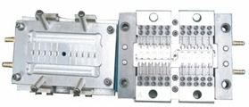
Standard two plates tooling – core and cavity are inserts in a mould base – "family mould" of five different parts
The mould consists of two primary components, the injection mould (A plate) and the ejector mould (B plate). These components are also referred to as molder and mould maker. Plastic resin enters the mould through a sprue or gate in the injection mould; the sprue bushing is to seal tightly against the nozzle of the injection barrel of the moulding machine and to allow molten plastic to flow from the barrel into the mould, also known as the cavity.The sprue bushing directs the molten plastic to the cavity images through channels that are machined into the faces of the A and B plates. These channels allow plastic to run along them, so they are referred to as runners. The molten plastic flows through the runner and enters one or more specialized gates and into the cavity geometry to form the desired part.
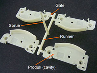
Sprue, runner and gates in actual injection molding product
The amount of resin required to fill the sprue, runner and cavities of a mold comprises a "shot". Trapped air in the mould can escape through air vents that are ground into the parting line of the mould, or around ejector pins and slides that are slightly smaller than the holes retaining them. If the trapped air is not allowed to escape, it is compressed by the pressure of the incoming material and squeezed into the corners of the cavity, where it prevents filling and can also cause other defects. The air can even become so compressed that it ignites and burns the surrounding plastic material.
To allow for removal of the moulded part from the mould, the mould features must not overhang one another in the direction that the mould opens, unless parts of the mould are designed to move from between such overhangs when the mould opens (using components called Lifters).
Sides of the part that appear parallel with the direction of draw (The axis of the cored position (hole) or insert is parallel to the up and down movement of the mould as it opens and closes) are typically angled slightly, called draft, to ease release of the part from the mould. Insufficient draft can cause deformation or damage. The draft required for mould release is primarily dependent on the depth of the cavity: the deeper the cavity, the more draft necessary. Shrinkage must also be taken into account when determining the draft required. If the skin is too thin, then the moulded part will tend to shrink onto the cores that form while cooling and cling to those cores, or the part may warp, twist, blister or crack when the cavity is pulled away.
A mould is usually designed so that the moulded part reliably remains on the ejector (B) side of the mould when it opens, and draws the runner and the sprue out of the (A) side along with the parts. The part then falls freely when ejected from the (B) side. Tunnel gates, also known as submarine or mould gates, are located below the parting line or mould surface. An opening is machined into the surface of the mould on the parting line. The moulded part is cut (by the mould) from the runner system on ejection from the mould. Ejector pins, also known as knockout pins, are circular pins placed in either half of the mould (usually the ejector half), which push the finished moulded product, or runner system out of a mould.
The standard method of cooling is passing a coolant (usually water) through a series of holes drilled through the mould plates and connected by hoses to form a continuous pathway. The coolant absorbs heat from the mould (which has absorbed heat from the hot plastic) and keeps the mould at a proper temperature to solidify the plastic at the most efficient rate.
To ease maintenance and venting, cavities and cores are divided into pieces, called inserts, and sub-assemblies, also called inserts, blocks, or chase blocks. By substituting interchangeable inserts, one mould may make several variations of the same part.
More complex parts are formed using more complex moulds. These may have sections called slides, that move into a cavity perpendicular to the draw direction, to form overhanging part features. When the mould is opened, the slides are pulled away from the plastic part by using stationary “angle pins” on the stationary mould half. These pins enter a slot in the slides and cause the slides to move backward when the moving half of the mould opens. The part is then ejected and the mould closes. The closing action of the mould causes the slides to move forward along the angle pins.
Some moulds allow previously moulded parts to be reinserted to allow a new plastic layer to form around the first part. This is often referred to as over moulding. This system can allow for production of one-piece tires and wheels.
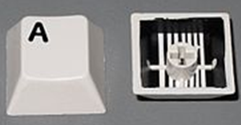
Two-shot injection moulded keycaps from a computer keyboard
Two-shot or multi-shot moulds are designed to "overmould" within a single moulding cycle and must be processed on specialized injection moulding machines with two or more injection units. This process is actually an injection moulding process performed twice and therefore has a much smaller margin of error. In the first step, the base color material is moulded into a basic shape, which contains spaces for the second shot. Then the second material, a different color, is injection-moulded into those spaces. Pushbuttons and keys, for instance, made by this process have markings that cannot wear off, and remain legible with heavy use.
A mould can produce several copies of the same parts in a single "shot". The number of "impressions" in the mould of that part is often incorrectly referred to as cavitation. A tool with one impression will often be called a single impression (cavity) mould. A mould with 2 or more cavities of the same parts will likely be referred to as multiple impression (cavity) mould. Some extremely high production volume moulds (like those for bottle caps) can have over 128 cavities.
In some cases multiple cavity tooling will mould a series of different parts in the same tool. Some toolmakers call these moulds family moulds as all the parts are related. Examples include plastic model kits.
Add:No.1 Hulanhe Road, Huangdao, Qingdao, China